Active Filters: Low-Pass, High-Pass, and Band-Pass
Active filters combine RC networks with op-amps so a signal can be filtered, buffered, and amplified in the same stage. They are common in sensor front ends, audio circuits, anti-aliasing paths, communication receivers, and control systems.
Learning Objectives
By the end of this lesson, you should be able to explain why active filters are used, calculate first-order cutoff frequency, compare low-pass, high-pass, band-pass, and notch behavior, choose a response type, and identify practical op-amp and component limits.
Why Use an Active Filter?
Passive RC filters are useful, but the load becomes part of the circuit. Active filters add an op-amp buffer or gain stage so the source sees high input impedance and the next stage sees low output impedance.
Use an active filter when you need:
- gain as well as filtering;
- buffering between a sensor and ADC;
- sharper roll-off by cascading stages;
- no bulky inductors at audio or low sensor frequencies;
- predictable response despite moderate load changes.
Avoid active filters when the signal exceeds the op-amp supply range, the frequency is beyond the op-amp gain-bandwidth capability, or a purely passive high-power filter is safer.
Basic Filter Types
- Low-pass filter: passes low frequencies and attenuates high frequencies.
- High-pass filter: blocks DC and low frequencies while passing higher frequencies.
- Band-pass filter: passes a defined frequency band between lower and upper cutoffs.
- Band-stop or notch filter: rejects a narrow unwanted band, such as mains hum.
At the cutoff frequency of a first-order RC section, output magnitude is 0.707 of the passband value, which is -3 dB.
First-Order Low-Pass Filter
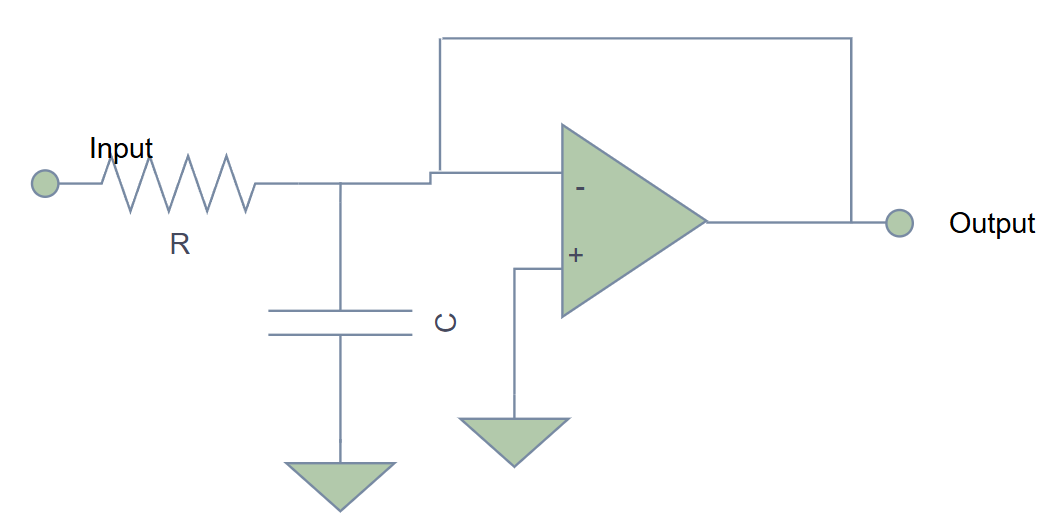
For a first-order active low-pass filter:
$$
f_c = \frac{1}{2\pi RC}
$$
$$
|H(f)| = \frac{A_v}{\sqrt{1 + (f/f_c)^2}}
$$
where fc is cutoff frequency in hertz, R is resistance in ohms, C is capacitance in farads, and Av is passband gain.
Above fc, a first-order low-pass filter rolls off at about 20 dB/decade.
Worked Example: Audio Subwoofer Filter
Goal: pass frequencies below about 200 Hz.
Choose C = 100 nF.
$$
R = \frac{1}{2\pi f_c C}
= \frac{1}{2\pi \times 200 \times 100 \times 10^{-9}}
= 7.96 k\Omega
$$
Use the standard value 8.2 kOhm. The actual cutoff is close to 194 Hz, which is acceptable for a simple audio crossover pre-filter.
Try It: Filter Cutoff Frequency Calculator
Enter any two values and leave the third empty.
Formula: `fc = 1 / (2 pi R C)`.
First-Order High-Pass Filter
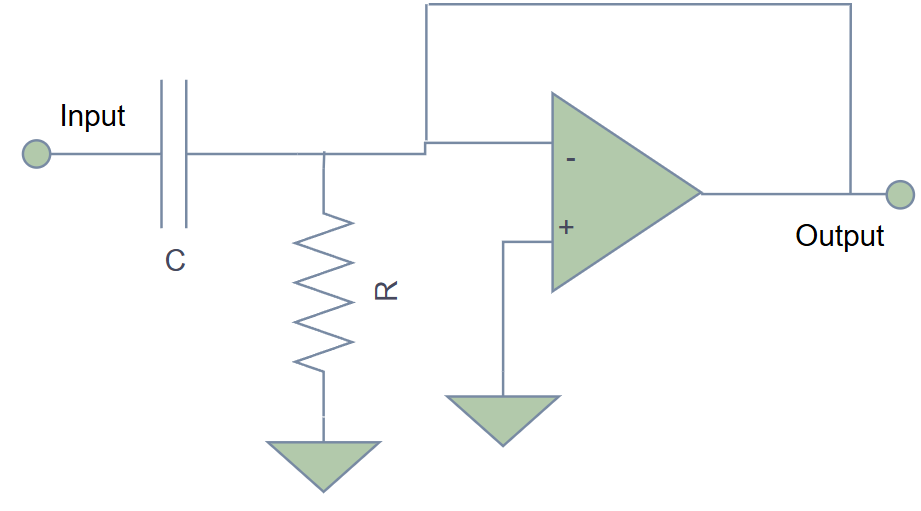
The cutoff formula is the same:
$$
f_c = \frac{1}{2\pi RC}
$$
The magnitude response is:
$$
|H(f)| = \frac{A_v(f/f_c)}{\sqrt{1 + (f/f_c)^2}}
$$
Below fc, the response falls at about 20 dB/decade.
Worked Example: Microphone AC Coupling
Goal: remove DC offset while preserving audio above 20 Hz.
Choose R = 100 kOhm.
$$
C = \frac{1}{2\pi f_c R}
= \frac{1}{2\pi \times 20 \times 100000}
= 79.6 nF
$$
Use 82 nF or 100 nF. If the source impedance is high, verify that the effective resistance is the input resistance seen by the capacitor, not only the labeled resistor.
Second-Order Active Filters
Second-order filters use two reactive components and roll off at about 40 dB/decade. A common low-pass or high-pass topology is Sallen-Key.
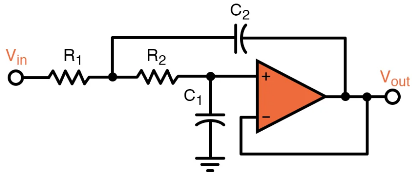
For equal component values in a simple Sallen-Key design:
$$
f_c = \frac{1}{2\pi RC}
$$
A Butterworth response is maximally flat in the passband. In the equal-component Sallen-Key case, it requires a non-inverting op-amp gain near:
$$
A_v = 1.586 = 1 + \frac{R_f}{R_g}
$$
Unity-gain Sallen-Key filters are easier to build and often useful, but their damping and cutoff shape differ from a Butterworth response.
Worked Example: Anti-Aliasing Filter
An ADC samples at 10 kS/s. Nyquist frequency is 5 kHz, so choose a low-pass cutoff around 4 kHz for a simple front-end filter.
Choose C = 10 nF.
$$
R = \frac{1}{2\pi \times 4000 \times 10 \times 10^{-9}}
= 3.98 k\Omega
$$
Use 3.9 kOhm or 4.02 kOhm. If using Butterworth Sallen-Key gain, choose Rg = 10 kOhm and Rf = 5.9 kOhm approximately.
Band-Pass and Notch Filters
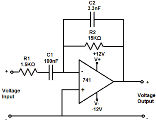
A simple wide band-pass filter can be made by cascading a high-pass stage and then a low-pass stage:
$$
BW = f_H - f_L
$$
where fL is the lower cutoff and fH is the upper cutoff.
For a voice-band filter from 300 Hz to 3 kHz, use a high-pass stage near 300 Hz followed by a low-pass stage near 3 kHz. Keep the stages buffered so one stage does not shift the other stage's cutoff.
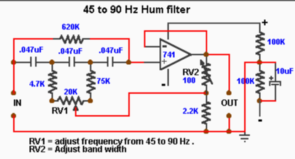
A notch filter rejects a narrow frequency. For a basic Twin-T notch:
$$
f_0 \approx \frac{1}{2\pi RC}
$$
For a 50 Hz notch with C = 1 uF, R is about 3.18 kOhm. Real notches are sensitive to component matching, so precision parts or trimming may be needed.
Choosing the Response
- Butterworth: flat passband, good general choice.
- Bessel: better phase linearity and transient shape.
- Chebyshev: sharper transition, but passband ripple.
- Notch: narrow rejection of a known interference frequency.
The best response depends on what matters most: amplitude flatness, time-domain shape, stopband attenuation, or transition width.
Practical Design Checks
- Keep resistors roughly between
1 kOhmand100 kOhmto limit loading and noise. - Use C0G/NP0 ceramic or film capacitors for accurate filters.
- Account for capacitor tolerance; X7R capacitance can change with DC bias.
- Check op-amp gain-bandwidth product:
GBWshould be comfortably higher thanclosed-loop gain x highest useful frequency. - Check slew rate:
SR >= 2 pi f Vpk. - Keep signal swing within the input common-mode range and output swing of the op-amp.
- Decouple op-amp supply pins close to the package.
Common Mistakes
- Calculating cutoff with nominal values and ignoring capacitor tolerance.
- Loading a passive stage with the next stage and shifting
fc. - Asking an op-amp with low GBW to implement a high-frequency high-gain filter.
- Using electrolytic capacitors in precision signal paths without checking leakage and polarity.
- Forgetting anti-alias filters before ADC sampling.
- Building a high-Q filter on a breadboard and then trusting the exact response.
Summary
Active filters give low-frequency circuits gain, buffering, and sharper response without inductors. The first-order cutoff formula fc = 1 / (2 pi R C) is the starting point, but the finished design also depends on topology, response type, op-amp bandwidth, slew rate, component tolerance, loading, and layout.
Further Reading
- Analog Devices, "MT-220: Analog Filters."
- Texas Instruments, "Active Low-Pass Filter Design."
- Microchip, "Anti-Aliasing, Analog Filters for Data Acquisition Systems."
- Walt Jung, Op Amp Applications Handbook, active filter chapters.